
Metal AM can be thought of as the placement of consecutive weld beads on the top of the previous ones. As such, AM and welding share common physics. Luckily, the welding literature contains a wealth of information on energy insertion, dynamics of the molten pool, development of the microstructure after solidification, effect on mechanical properties and residual stress generation.
Due to analogies among the simulation of beam-based welding technologies, relevant basic methods are being adopted and specifically extended to the application in laser-aided and electron-aided metal additive manufacturing processes.
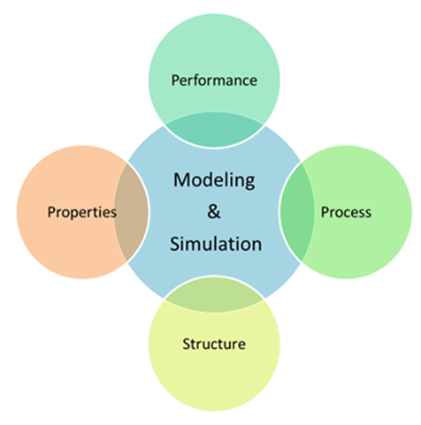
Modeling a complex problem often requires dividing it into smaller ones… This holds true for metal AM!
To effectively model across multiple scales, from molecular to macroscopic, it may be more efficient to build and operate models appropriate to each scale level and then integrate them or couple them through data sharing. This will become easier to accomplish as the cost of computing infrastructure continues to decrease.
The full course of phenomena occurring in less than a second during SLM/EBM can be decomposed in several major topics. They are presented according to their chronology or energy flow in the additive process:
- energy insertion,
- molten pool dynamics,
- microstructure evolution,
- residual stress and distortion,
- prediction of material properties.
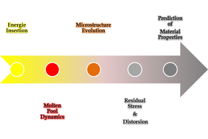
Chronology of some inter-dependant physical phenomena occuring during the deposition of each layer. Each is a topic for modeling & simulation and is characterized by particular time and space scales.
Each section is critical to the model. In fine, assumptions and simplifications made anywhere will impact the desired outcomes of the simulation: estimation of residual stresses, distortion, material properties…
1) Energy insertion
Laser melting process is characterized by highpower density and short interaction time. While laser-based energy sources are at the core of literature on the subject, main observed physical phenomenon can be extended to EBM. They include keyhole energy physics, losses of energy to vapor clouds and losses of material through sublimation.
Basically, a model of the energy beam has to accurately describe the physics and timing of the real system because the temperature distribution calculated will determine residual stress fields and microstructural evolution.
Modeling of the energy beam, molten pool cavity and energy absorption show that energy flux is governed by focal spot location, energy distribution at the focal spot, and convergence angle.
Beam geometry variations affect temperature distribution which in turn affects the molten pool depth, undercooling rates, microstructure, residual stress, and distortion. As using different beam geometries produces different sets of energy density and thermal distribution, using different energy source models will results in dissimilar thermal distributions in the substrate. For laser energy sources for example, a pulsed model (with a parabolic heat distribution) will more accurately predict thermal distribution than a static Gaussian (bell curve) distribution, for example.
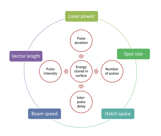
Laser melting process parameters and material properties influence various physical phenomena (energy penetration, heat conduction and radiation, capillary forces and wetting, melting/solidification, Marangoni’s mass flows, distortion, etc.).
The simulation and validation of the effect of energy density on Marangoni effect and energy penetration is an important step in SLM process modeling. “Marangoni convection”, also called surface-tension-driven convection (or thermo-capillary convection) is a well-known phenomenon (issue) in laser melting.
Marangoni mass flows are owed to gradients of surface tension (capillarity) and since surface tension is a function of concentration and temperature, thus two types of Marangoni flows can be triggered, thermal and solutal Marangoni flows (or thermos-capillary and solute-capillary flows).
Marangoni effects are of primary importance in SLM because they may affect dramatically the melt pool geometry. For instance, when the liquid pool gets larger than the beam diameter (due to higher laser power), Marangoni whirls appear at the periphery of the molten pool (due to large surface thermal gradients). Whirls’ convection largely affects the traces by widening or deepening the melt pool at their center.
The influence of Marangoni convection can lead to form craters or alter layer roughness which is a signature of improper laser processing conditions. Proper multi-physics modelling and processing parameters (beam power and scanning speed) can be validated experimentally by giving a smooth and continuous track.
2) Melt pool dynamics
To ensure a relative control on part quality, it is essential to know, study or simulate the relationship between process parameters and the geometry of the melt pool. It allows to establish an "envelope" containing proper ranges of values for each process parameter.
Because the melt pool geometry strongly affects microstructures when it solidifies, two key parameters of the melt pool geometry are its cross-sectional area and length-to-depth ratio.
Practically, analytical and numerical methods are used in main metal AM techniques to draw maps of curves of constant melt pool cross-sectional area and constant length-to-depth ratios over specific ranges of power and velocity of the electron or laser beam.
Such process maps support engineers to select a beam power and a scan speed for user-specified values of a deposition rate or melt pool cross-sectional area and length-depth ratio.
To maintain the melt pool length-to-depth ratio with a beam of constant diameter, the beam power and velocity are increased or decreased simultaneously. To maintain the melt pool cross-sectional area, the beam power and the beam velocity are changed oppositely.
Very useful information about the melt pool evolution (during the heating-cooling cycles) can be derived from experimentation through the studies of process parameters and part microstructures.
3) Microstructural evolution
Developing an accurate and sufficient representation of the microstructure obtained in metal AM is critical to estimate material properties with a good precision. It will also allow component performance to be further tailored and optimized for its function.
Thermo-mechanical processing of metal alloys can create various distinct microstructures, depending on material’s sensibility and baro-thermal conditions. In general, the microstructure obtained after solidification tends to become more dendritic with increase in beam power because this creates a greater temperature gradient. It coarsens with an increase in heat input per unit length. In addition, the nature of the microstructure varies also with the spatial variation of the cooling rate and thus, with the location within the part.
There are not so many studies concerning the origin and the evolution of the microstructure during SLM. Such investigations have crucial importance for the acceptance of SLM as a viable alternative manufacturing method.
Numerical methods “Lattice Boltzmann” (LB) and cellular automata (CA) have already been combined or used independently to simulate solute-driven dendrite growth. Compared to finite element and finite volume approaches, LB/CA combination is easily parallelized and exhibits good parallel scalability, necessary attributes to scale the computation to macroscopic levels, handle several types of grain evolution and include molten pool fluid flow and temperature calculations.
In practice, any processing parameter that would affect the energy density (such as laser power, scanning speed, etc.) and thermal history may influence the microstructure development.
For example, scan vector length (i.e. using a checkerboard scan strategy) has a significant effect on the microstructural formation during SLM. Applying the checkerboard with a reduced island size can reduce the cooling rates and thus presumably produce parts with lower residual stresses. On the other hand, the re-melting of each deposited layer (double scan strategy) has a minor influence on the microstructure of the sample (i.e. it produces a slight coarsening of the grains) but decreases the build rate considerably and increases significantly the energy consumption.
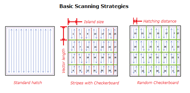
Some examples of different scanning strategies. Advanced strategies derive from these basic concepts.
4) Residual stress
Thermal powder-bed techniques such as SLM and EBM still have to deal with several process deficiencies compared to conventional manufacturing technologies but extensive technical progresses have been made in recent years.
The locally concentrated energy input gives rise to a temperature gradient mechanism (TGM) which is a major issue because the residual stresses result in crack formation and part deformations. In case of SLM, the crack formation can provoke a disconnection of parts from the building platform. Shape accuracy and mechanical strength are influenced thereby.
Finite element numerical analysis, by the means of adequate algorithms helps cope with these challenges and bring more thermal control in metal AM processes, critical for obtaining consistent build conditions and limit residual stress-induced tolerance losses.
Residual stress and deformations are very dependent on material behavior. Moreover, above a certain limit, strong nonlinearities that characterize large deformations make modeling even more difficult.
For deposition onto a room temperature substrate, changing laser velocity and power can reduce residual stresses. Beyond sufficient level of preheating, residual stress reduction becomes a very weak function of laser velocity and power. Indeed, substrate (and walls) preheating is more effective to decrease thermal gradients than changing laser power and velocity (which may alter pool melt size).
The biggest pay-off in reducing residual stresses comes from uniform base plate preheating.
5) Mechanical properties prediction
Mechanical properties of additive manufactured components are greatly dependent on the microstructure, which, in turn, greatly depends on the thermal history. While there is some correlation between thermal history and bead dimensions (single beads deposited are the fundamental unit of multi-layered components manufactured by an additive process), hardness measurements do not necessarily correlate with thermal history.
Parts produced by EBM and SLM are generally tested for two important mechanical properties, namely tensile strength and fatigue life. Hardness is a good approximation of the tensile strength while fatigue life is particularly essential in some industries such as Aerospace. It is then essential to ensure that sufficient loading cycles can be achieved before failure occurs.
Numerical finite element methods are developed and attempts are made to optimize the process input parameters (laser scanning hatch pattern and speed, energy input power, part orientation, powder size) for those critical mechanical properties.
The test direction through which tensile test are performed shows a major effect on the tensile strength (and yield stress) than the change of process parameters.
Indeed, tensile properties measured along the wall building direction (parallel to the direction of grain growth) are significantly higher than across the grains. It mainly results from the anisotropic property of the deposition and applies for both deposited and stress relieved parts.
Process parameters play a second role. For a given laser power, the parts built with a higher traverse speed exhibit similar or slightly higher hardness than those built with lower traverse speed.
Mechanical properties of the deposited parts match the properties of wrought and as cast material. It is important to note that the tensile properties often depend stronger on the test direction than on the process parameters.
A certain level of prediction can be attained with empirical models derived from design of experiments (DOE) approaches. These models are based on process parameters and structural data obtained from additive manufacturing or wielding (ultimate tensile load, weld hardness and toughness). Genetic algorithms are also used to search for process parameters that meet desired combinations of mechanical properties.
Conclusion
Inherent trade-offs between achieving fast processing timings, fully dense, relatively stress free structures and good mechanical properties have generated a demand for process optimization.
Ultimately, finite element (FE) and finite volume (FV) methods are useful numerical approaches when applied to additive manufacturing process. They offer the ability to predict effectively thermal fields and thus, residual stress and distortion. However, great care is needed when choosing simulations parameters (mesh density, solver type and “time step” of the simulation).
An algorithm that solves a well-conditioned problem may be either numerically stable or numerically unstable. An art of numerical analysis is to find a stable algorithm for solving a well-posed mathematical problem.
Eventually, as for any sort of modelling, a degree of validation (through experiment or data analysis) must be exercised to increase confidence in what is being modeled.