
Mechanical Tests Ensure the Reliability of FMGC Protecting and Ballasting Shells for Subsea Cables
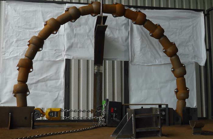
Bending Test on the FMGC Portecting and Ballasting Shells for IBOCS
As part of its product development strategy, FMGC has deeply studied the mechanical properties of the protecting and ballasting shells for submarine cables.
The shells are a versatile & high efficient solutions to protect and stabilise the cables in the following conditions:
- Onshore landing area
- On-crossing sections
- On-rocky seabed
The shells can also be part of a complete cable protection system, used to protect the cables on the dynamic area between the seabed and the interface of the foundations.
Every time when a part of the range of shells is developed and manufactured by FMGC, several tests, as tensile, bending and impact tests are achieved to ensure the mechanical properties of the shells and their ability to meet the project requirements.
As part of its product development strategy, FMGC is also able to design, develop and provide dedicated shells to meet specific requirements.
All these tests deliver technical data recognizing the reliability and the durability of the FMGC cast iron shell system for subsea cables protection.
A Revolutionary Solution – FMGC Protecting and Ballasting Shells
The main idea of the design of the FMGC protecting and ballasting shells for submarine cables is to combine the protecting, the stabilizing and the bend restrictor aspects in only one solution. This specific design contributes to an important cost reduction while providing:
- Sufficient weight per meter to maintain the stabilization of the cable on the ground without resorting to external elements as concrete mattress or rock-dumping;
- An increase in the stability of the cable and a reduction of the fatigue of electrical conductors;
- An increase in the bending radius in order to get closer to the bending radius of the cable and to follow the relief of the seabed and thus still improve the stability and the fatigue of the cable;
- A transfer of loads from the cable to the CIS during installation;
- A possibility to assemble shells with different weight (same diameter) without resort to transition pieces.